| This NSF-funded project seeks to provide methods to embed into a physical object information for a variety of purposes, including genuinity detection, tamper detection, and multiple appearance generation. Genuinity detection refers to encoding fragile or robust signatures so that a copy, or tampered, version can be differentiated from the original object. Multiple appearance generation refers to generalizing the encoded information from a signature to a different appearance of the same physical object. The project also includes the development of underlying infrastructure for 3D model acquisition and for appearance/signature creation and extraction using projector-based illumination. |
| Overview |
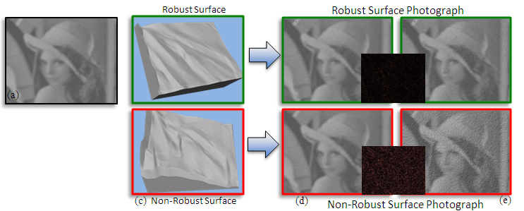
| We extend the below mentioned “hidden relief” work to a novel scheme to robustly embed additional information onto physical objects. The motivation behind this approach is to make the 'signature' hard to remove so that the object is resilient to wear-and-deform, deformations, and copying. In our method so far, we use as a 'signature' an arbitrary image and then use a computational optimization approach to obtain the surface geometry that achieves both the appearance goals and the robustness goals. The signature is made visible when the object is subjected to a particular type of (projector-based) patterned illumination. Our setup consist of one camera to capture a photograph of the object and one projector that provides lighting. We embed a image (e.g., Lena in the following figure) onto the object. We embed the image in both a robust way and a normal way (e.g., naively alter the object shape to yield the desired appearance/shading). Both objects/ways are able to show the embedded image when there is not much change in the geometry. However, when there is a change in the object geometry, the appearance remains mostly unchanged with our robust embedding while such is not the case with normal embedding. The tTop row of the following figure shows simulated photographs of the robustly embedded object and the bottom row shows normal embedding. We have also demonstrated this with several manufactured objects. |
 |
To embed an appearance/signature image robustly onto objects, we design the objects according to the following requirements.
- Appearance Requirement: the surface appearance should mimic, as best as possible, that of a predefined signature when illuminated from a pre-determined direction.
- Robustness Requirement: the signature appearance should be robust up to a pre-selected amount of surface change
- Projection Requirement: the signature appearance should be visually evident when the surface is illuminated by a specifically-designed digital light pattern. |
| Process |
| Our process follows the aforementioned three requirements. We show the results of each step based on each requirement in the following figure. At the beginning, we place the input signature image (the violin image). Based on the appearance requirement, we calculate an object geometry whose appearance mimics the signature image as best as possible. The robustness requirement then comes into play and we modify the geometry so that the appearance will be resistant to a specified amount of geometric changes. Next, we calculate the projector pattern needed to minorly alter the appearance of the object to then be “identical” to the signature image. Finally, we project the light pattern onto the object geometry and obtain the actual signature appearance/photograph. |
 |
| Results |
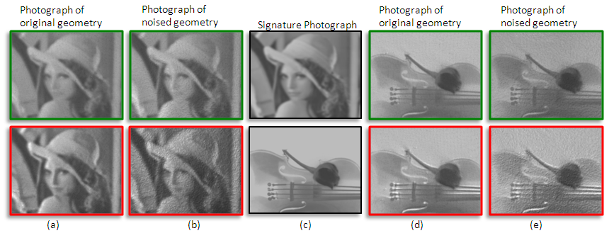
| Here we show a real-world photograph of robustly embedding objects and normal embedding objects for two different signature images. The signature images are shown in the center column ©. Top row shows the real-world photograph of robust embedding objects. Bottom row shows the normal embedding objects. Both of them are able to show the signature photograph with the original fabricated objects (column (a) and (d)). When there is noise/changes introduced to the objects, the robust embedding objects remain unchanged while normal embedding objects has undesirable artifacts as shown in the photographs. This is shown in column (b) and (e). |
 |
| Overview |
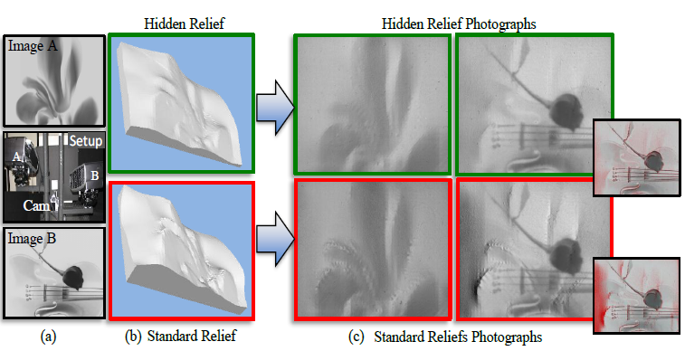
| We present a modeling process, coupled with automated 3D fabrication, for creating hidden reliefs. Our relief surface produces a first grayscale appearance visible by simple direct illumination and a second grayscale appearance ensured to be visible when the relief is lit by a digital projector with a specifically designed pattern and from a particular direction. The two appearances can be arbitrarily different yet embedded in the same physical relief. While in some cases it might be easy for a projector to impart a second (hidden) appearance on a relief, projectors have limited power which in turn limits the range of second appearances. Moreover, the object must maintain a geometric surface compatible for generating the second appearance. Our method to design a relief maintains the properties needed for producing an arbitrary second appearance while also ensuring the first appearance is visible under direct illumination. The following figure shows a comparison between our hidden relief and a standard relief. A standard relief (bottom row in the figure) shows only image A in subfure (a) under simple directional lighting. It is not able to show image B since projectors have limited intensity range. Hidden relief (top row in the figure) shows image A with simple directional light but also shows image B under designed projector pattern. The figure shows that hidden relief shows both appearances while standard relief has artifacts in it when showing image B. |
 |
| Here we show the diagram of our proposed system. We geometrically calibrate our two projectors and one camera beforehand. The computation of the hidden relief is based on geometric calibration parameters and two appearance images (image A and B). Next step, we compute the relief geometry and the projector pattern to produce image B. We simplify the original formulation and achieve a linear computation that performed iteratively will give us both the relief geometry and the projector light pattern. After several iterations, we have the geometry computed and an automated process is used to fabricate the 3D physical object. The fabricated physical object is then used to perform radiometric calibration which matches projector intensity range to camera response range. At the end, we calculate the proper light pattern according to radiometric calibration results. Now we project the pattern onto the object and see the second appearance hidden in the relief. |
 |
| Results |
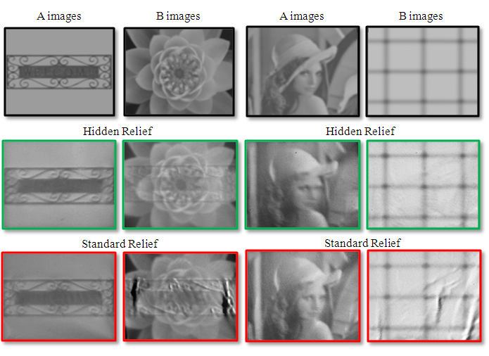
| Here we show real-world photographs of hidden reliefs and standard reliefs for comparison. We fabricated hidden reliefs and standard reliefs. Then, radiometric calibration is performed for each object and the best light patterns that we can use are computed. In the following figure, we show results with very different input image A and image B. Hidden reliefs are able to show those two images while standard reliefs are only good in showing image A. |
 |
| Summary |
We have also worked on a 2D version of the problem: the genuinity of printed documents. This should not be thought of as easier than the 3D manufacturing problem, because there are fewer opportunities for embedding genuinity signals, and the available channels turned out to be very noisy (i.e., our own printing of the genuine document can erase the genuinity signal – but we have overcome this difficulty now).
We have what looks like a very promising solution (being tested) for the problem of genuinity of printed documents. For the yes/no version of the problem (i.e., genuine printed page or not) we use a technique pioneered by our Purdue ECE colleague Ed Delp and his group to embed a large number of binary 'genuinity votes' in a printed page, a majority of which (around 70%) survive our own printing process. An adversary's scanning of a marked document and re-printing it (possibly after unauthorized alterations) would be detectable because it would entail another round of 30% loss of the binary genuinity votes. We have extended the scheme to go beyond detecting non-genuine printouts, to also pinpoint where in the page unauthorized alterations have been made. Specifically, if the page is a contract or form that can be partitioned into N known sensitive sections (e.g., date, dollar amount, name of beneficiary, signature, terms of delivery, etc) then we can pinpoint which of those were fraudulently modified after scanning the original and re-printing the altered (non-genuine) version. The ongoing experimental evaluation of our scheme is expected to take a few more months of work, and Professor Delp and 2 of his senior PhD students will be co-authors of resulting papers. |
| Overview |
| Our initial work provided a way to embed fragile signatures into physical objects. The approach provides an algorithm for encoding into a digital 3D object information that enables determining genuinity of a physical object after its automated manufacturing and it being copied by an adversary even if the adversary has copying and manufacturing technology superior to the original manufacturer. In today's technological world, many physical objects are manufactured using 3D computer graphics models and digitally controlled devices (e.g., milling machines, 3D printers, and robotic arms). The manufactured objects can range from inexpensive steel screws to costly and carefully designed parts, for example, for engines and for medical instruments. Our algorithm provides a way to encode a unique signature into a computer-designed and fabricated object and a way to decode the signature in order to verify object genuinity. The following figure shows the overview process of our design. |
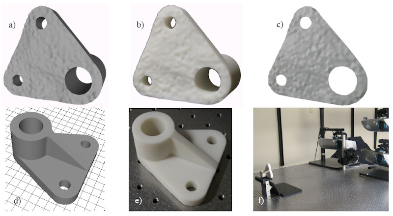 |
| (a,d) Computer-generated signature as per user specifications which is embedded into a subset of the object. (b, e) The automatically manufactured physical object. (c, f) An automated verification system determines whether it is genuine or is a copy |
| Signature Design |
| The design of the genuinity signature includes the following steps. First, the user selects a footprint area where the signature should be. Then a smooth displacement is generated automatically and randomly. This is called the mean displacement. In the next step, we introduce a randomly assigned grouping. A specific “variance” value is assigned to each group. Then, the variance displacement is generated according to the assigned variance and is added to the mean displacement. In the end, each displacement is the sum of mean displacement and variance displacement. Also, the grouping is kept secure so the adversary has no way to figure out what/how variance was embedded. Now with the 3D model of the object with signature, an automated manufacturing process fabricates a 3D physical object. |
 |
| Signature Verification |
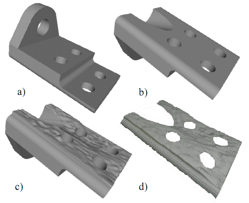
| The verification process determines whether a given copy is a genuine one from our own production or a replicated one from the adversary. Since the signature is embedded in the 3D displacement of the object, a 3D acquisition process is needed to obtain the 3D geometry of the given object. Another example is shown in the following figure. (a, b) are top and bottom view of the 3D synthetic model. c) is the model with signature at the bottom. (d) shows the 3D acquisition of the signature footprint. |
 |
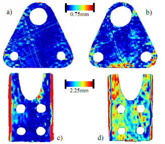
| With the 3D geometry of the given physical object, now we are able to verify the genuinity of the object by using a stochastic analysis. The following figure shows the differences between the acquired surface fragment and the signature digital model. Top row shows the difference of genuine objects and bottom row shows replicated objects. As seen in the figure, replicated objects have much larger differences than genuine objects. Thus, we can determine whether an object is genuine or not. |
 |
 Research supported in part by NSF CNS Grant No. 0913875 Research supported in part by NSF CNS Grant No. 0913875 |
| Publications |
- Yi-Liu Chao, Daniel Aliaga, "Dual Appearance Reliefs Paper (title altered, anonymous submission)", submitted, 2011.
- Yi-Liu Chao, Daniel Aliaga, "Embedding Signatures Robustly Onto Objects", IEEE Transactions on Pattern Analysis and Machine Intelligence, in preparation, 2011.
- Daniel G. Aliaga, Mikhail Atallah, "Genuinity Signatures: Designing Signatures for Verifying 3D Object Genuinity", Computer Graphics Forum (also EUROGRAPHICS), 28:2, 437-446, 2009.
PDF
- D. Aliaga, Y. Xu, "Photogeometric Structured Light: A Self-Calibrating and Multi-Viewpoint Framework for Accurate 3D Modeling", IEEE Computer Vision and Pattern Recognition, Jun., 2008.
PDF
MOV
|
| People |
- Daniel Aliaga - Faculty
- Mikhail Atallah - Faculty
- Yi-Liu Chao - Graduate Student
- Alvin Law - Graduate Student
- Shriphani Palakodety - Undergraduate student
- Tyler Smith - Undergraduate student
|

|


